home automation the hard way
The secret to finishing any side project is to understand that it will never be finished. Embrace that fact and just get the most basic version working, then figure out the next step, make it better, rinse, repeat. I’ve done that for about 15 years on this project… through eight full iterations.
I could have probably done this far “easier” by just buying off the shelf components and hubs, but every bit of off-the-shelf hardware I’ve used has been a letdown. I don’t trust third party cloud solutions with security, and I’ve been doing this long enough to know they all either go out of business, break their integrations, get bought out and disappear, etc.. These companies all want walled gardens and to be honest, their stuff isn’t even very good.
So, I’ve been on a quest. And now on my ninth iteration, I’m ready to share it with other nerds who might find it useful, because I’ve fought through all the hard stuff already so you hopefully don’t have to. All of my code, tooling, etc., will be on github and open source, and while this isn’t going to be beginner friendly, I think newbies will be able to follow along and learn a lot.
Requirements
Initially, I wanted devices to be able to report data to a server directly via HTTP/JSON, then MQTT, etc. At one point I had units pinging an Amazon Lambda function to report data and wrote a custom reporting / alerting / control interface. All fun experiments and diversions, and through each one I was able to at least reliably read sensor data from the nodes. These days, I really like Home Assistant and am optimizing for low power nodes that can quickly report using radios and go back to sleep. Control nodes (garage door, switches, etc.)will likely be powered by 5v supplies and not sleep.
- No vendor lock-in, of any kind. So, no zigbee or other “hub” devices.
- No cloud services or external dependencies; everything must be local network.
- Must able to register nodes into the network and configure in Home Assistant easily.
- Must be able to swap and introduce new types of sensors/nodes/controls without affecting other nodes.
Remote access to Home Assistant is be handled using WireGuard VPN, which is out of scope for this post but worth noting.
Hardware
I’ve experimented with a dozen off the shelf microcontrollers and designed my own boards using ATTiny85s. Lately I’ve been using the Xiao ESP32-C3 and ESP32-C6 microcontrollers and have been very happy with them. They’re reasonably inexpensive in bulk (~$5/each from Seeed, $12/each from Amazon), have more than enough power for this project, and have a variety of antenna options. Every other ESP module I used had quirky sleep issues or used too much power generally. The Xiao series wins in every category, and since I’ll be using ESP-NOW for the network protocol, some of the old ESP units will still be usable as wired nodes.
Nodes will use SEEED Studio Xiao ESP32-C3 [Seeed] [Amazon] and ESP32-C6 [Seeed] [Amazon] microcontrollers with a variety of antenna options. Nodes close to the exit will be able to use onboard antennas, while nodes further away will need to use external antennas [Seeed] [Amazon]. Range tests across my property show that I can get to the furthest back corner of my property with the rod antenna.
I’ll likely design custom boards and 3d print enclosures for the nodes - the Xiao units use castellated edges, so it’s easy to solder them permanently or snap them into a socket.
Framework & Software
Most people go through a progression of tooling and deployment workflows as they get more comfortable with Arduino / ESP32 development. I used vim, then emacs exclusively in web development, so switching back to neovim isn’t too big of a jump for me and I like being able to automate builds and deployments with simple keystrokes.
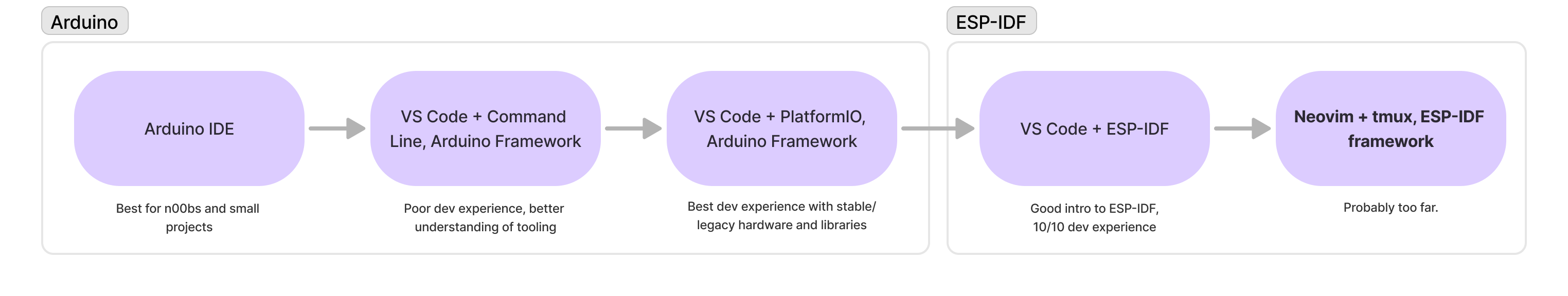
Arduino Path:
- Arduino IDE → The simplest option for getting started.
- VS Code + Command Line (Arduino Framework) → Adds better editor features and encourages better coding practices, tricky to set up.
- VS Code + PlatformIO (Arduino Framework) → Great editor features, library support for stable / legacy hardware, and build chain.
ESP-IDF Path:
- VS Code + ESP-IDF Framework → Nightmare to set up & wrap your head around at first. Limited library support, but good core.
- Neovim + tmux + ESP-IDF → Mostly personal preference here to get back to neovim and tmux.
The biggest problems I ran into with the Arduino IDE and frameworks are the layers of abstraction added to “simplify” things. Arduino trades understanding for convenience in many cases, so if you want to get RGB leds to do something fun, you just grab the library, change a few examples, and pray that your pin mappings actually line up. I found with a big enough project that I needed to understand the underlying hardware and software to be satisfied with any of it.
PlatformIO tries to solve a lot of the issues, and does a great job with stable/legacy hardware. It has the same “black box” problem, but it’s easier to use PlatformIO to install a specific version of a library if you need to, and I found it far easier to debug. The deployment pipeline is pretty great as well.
ESP-IDF was immediately a bit overwhelming, but I knew I had to get into it to reach the next level of understanding. I’m still early on with it, but I’ve noticed my code has improved significantly as I read the actual library code and think through the technical details, vs plugging into off-the-shelf libraries and praying. My goal is to use the fewest dependencies possible and continue improving my C/C++ skills. I think this is the push needed to get there.
Network Protocol
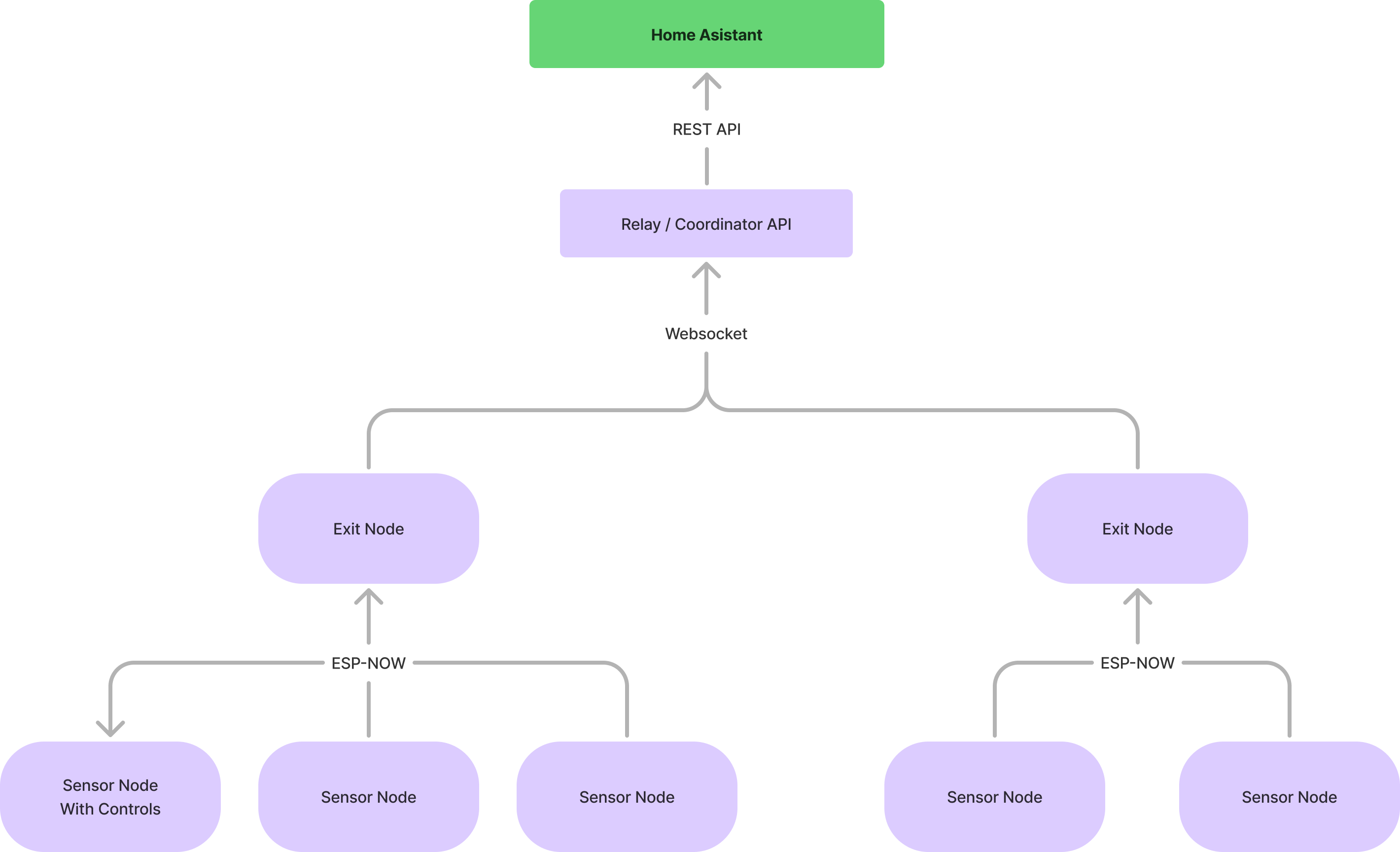
Nodes communicate using the ESP-NOW protocol up to an exit node. The exit node will be an ESP32-C6, which can operate in both ESP-NOW and Wifi modes and maintain a websocket connection to the controller.
Data Format
ESP-NOW is limited to 250 bytes of payload so using JSON would be a bit ridiculous. In a previous iteration, I designed a binary payload with fixed-position fields for each node type. This worked well, but was a bit inflexible - any time I changed the payload, I had to update the exit node with parsing, handle versioning, and update each node. Sounded like a good idea at the time, but I immediately realized I went too far. Several years ago, I learned about TLV (Tag-Length-Value) when working on processor certifications for EMV card readers and fell in love with the format. It’s simple, flexible, and by defining my own tags I can easily add new sensor data types without breaking anything. Each node can have a different set of tags / sensor types and the receiver and controller parse it without needing to know very much about the details.
0x01 – Packet Length (1 byte)
Defines the total length of the entire TLV message in bytes. This ensures the receiver knows where the packet ends.
Example: 17 (bytes) → 0x01 0x11
0x10 – Node ID (1 byte)
A unique identifier for the node, ranging from 1 to 255. This allows the receiver to distinguish between different sensor nodes.
Example: 28 (0x1C) → 0x10 0x01 0x1C
0x11 – Counter (1 byte)
Indicates the number of attempts made to send this packet. Maximum value is 10.
Example: 3 (0x03) → 0x11 0x01 0x03
0x12 – Firmware Version (1 byte)
Represents the firmware version running on the node. Useful for debugging and ensuring compatibility.
Example: 1 (0x01) → 0x12 0x01 0x01
0x13 – Voltage (1 byte)
Indicates battery voltage in 0.1V steps. A value of 47 corresponds to
4.7V. Maximum measurable voltage is 25.5V.
Example: 4.7V (0x2F) → 0x13 0x01 0x2F
0x20 – Temperature (2 bytes)
Represents temperature in 0.1°F steps, allowing for precise readings. Supports a range from -32,767°F to +32,767°F.
Example: 65.5°F (0x028F) → 0x20 0x02 0x02 0x8F
0x21 – Humidity (2 bytes)
Reports humidity as a percentage, encoded in 0.1% steps. Supports values
between 0.0% and 100.0%.
Example: 45.0% (0x01C2) → 0x21 0x02 0x01 0xC2
0x22 – Soil Moisture (2 bytes)
Represents soil moisture as a percentage in 0.1% steps. This allows for
granular readings between 0.0% and 100.0%.
Example: 30.0% (0x012C) → 0x22 0x02 0x01 0x2C
0x23 – Luminosity (2 bytes)
Measures light intensity in lux. Supports a range of 0 to 65,535 lux.
Example: 1000 lux (0x03E8) → 0x23 0x02 0x03 0xE8
0x30 – Switch State (1 byte)
Represents a binary ON/OFF state. 0x00 indicates OFF, while 0x01 indicates
ON.
Example: ON (0x01) → 0x30 0x01 0x01
Data Packet Example
# Sensor Readings / Values:
Node ID: 28
Counter: 3
Version: 1
Voltage: 4.7V
Temperature: 65.5F
Humidity: 45.0%
Soil Moisture: 30.0%
Luminosity: 1000 lux
Switch State: ON
| TLV Tag | Length | Value | Hex Value | Encoded Field |
|---|---|---|---|---|
| 0x01 (Packet Length) | 1 | 32 bytes | 0x1F | 0x01011F |
| 0x10 (Node ID) | 1 | 17 | 0x11 | 0x100111 |
| 0x11 (Counter) | 1 | 28 | 0x1C | 0x11011C |
| 0x12 (Firmware Version) | 1 | 3 | 0x03 | 0x120103 |
| 0x13 (Voltage) | 1 | (4.7 * 10) = 47 | 0x2F | 0x13012F |
| 0x20 (Temperature) | 2 | (65.5 * 10) = 655 | 0x028F (Twos Complement) | 0x2002028F |
| 0x21 (Humidity) | 2 | (45.0% * 10) = 450 | 0x01C2 | 0x210201C2 |
| 0x22 (Soil Moisture) | 2 | (30.2% * 10) = 302 | 0x012E | 0x2202012E |
| 0x23 (Luminosity) | 2 | 1260 | 0x04EC | 0x230204EC |
| 0x30 (Switch State) | 1 | 1 | 0x01 | 0x300101 |
Resulting Packet:
0x01011F10011111011C12010313012F2002028F210201C22202012E230204EC300101
Additional Considerations
TLV field for matrixed switches / LEDs / binary sensors
Using a full byte (8 bits) to store a single binary sensor state (e.g., 0x30 0x01 0x01 for ON/OFF) is wasteful when multiple switches, LEDs, or sensors can be encoded into a single byte. Instead of using a whole byte per sensor, we can group multiple states into a bit-packed format, reducing message size and improving efficiency.
Let’s take an example where a node has four switches. Instead of sending
four separate bytes, we pack them into a single byte, where each bit
represents a switch state (1 = ON, 0 = OFF).
| Switch | State | Bit Position | Bit Value |
|---|---|---|---|
| 1 | On | 0 | 1 |
| 2 | Off | 1 | 0 |
| 3 | On | 2 | 1 |
| 4 | Off | 3 | 0 |
This results in:
- Binary Representation:
0b00001011 - Hexadecimal Value:
0x0B
TLV Encoding Format
| Tag | Length | Value | Encoded Field |
|---|---|---|---|
0x33 |
1 byte |
0x0B |
0x33 0x01 0x0B |
In TLV format, this means:
0x33→ Tag for switch states0x01→ Length (1 byte)0x0B→ Value (bit-packed switch states)
Exit Nodes
ESP32 C3 and C6 microcontrollers can operate in both ESP-NOW and Wifi modes. The ESP32-C6 will be used as the exit node for the network and will maintain a websocket connection to the Relay / Coordinator API to deliver data & send instructions to controller nodes. If this turns out to be unreliable, I have two backup plans that would still be easy to implement and that don’t change my overall direction:
- Use an ESP32 that has ethernet built in.
- Exit nodes could feed data to a raspberry pi over GPIO Serial; raspberry pi could also host the Relay / Coordinator API. (This pi could also host Home Assistant, though I have other systems already set up for that)
Relay / Coordinator API
Most ESP-based nodes I’ve seen that talk to Home Assistant do so using an integration called ESPHome. It’s a great project when getting your feet wet, especially if you’re comfortable with a ton of nodes being on your wifi network. I’m getting away from that, so I’ll need another way to get data into Home Assistant.
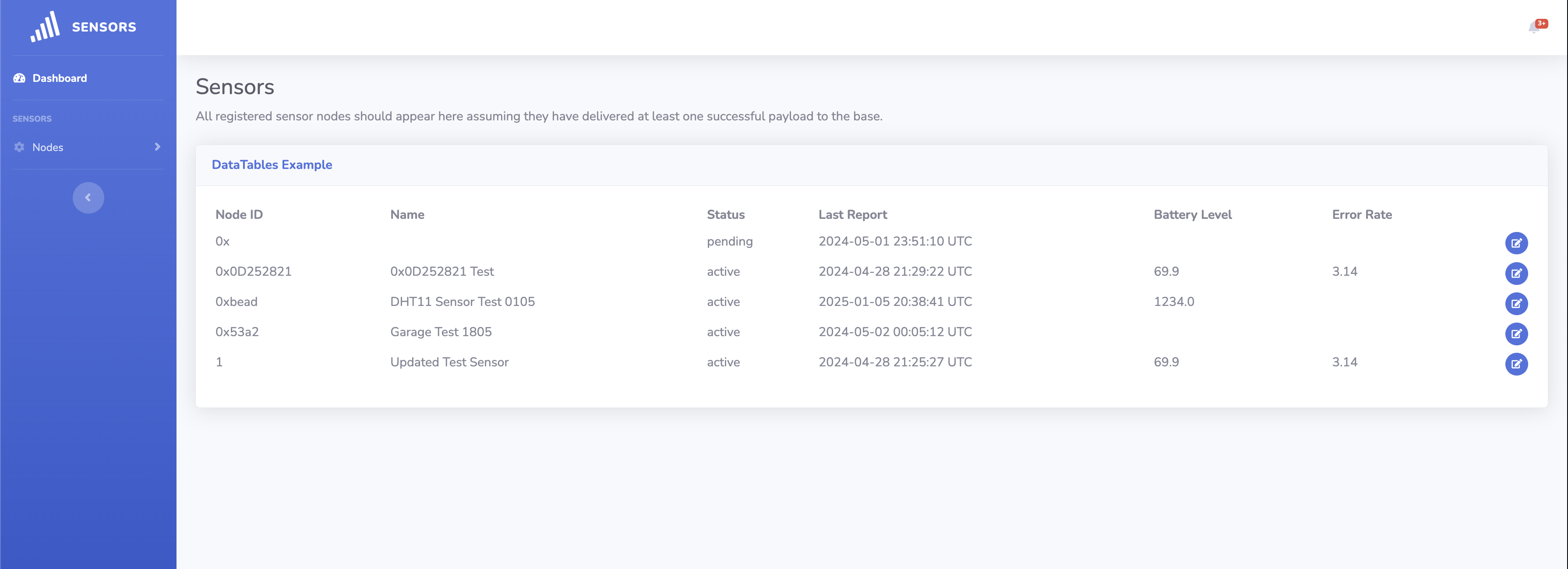
The controller I built is a Rails app using React and sqlite database. The rails app hosts a websocket that exit nodes connect to. When an exit node receives a packet, it parses the TLV data, identifies the node, and if the node has been registered in the controller, it passes the data to Home Assistant. If the node hasn’t been registered, it records the fields, marks the node as pending, and waits for me to complete the registration process, which consists of looking at the fields and making sure the data is going to be formatted correctly when the controller onboards the node in Home Assistant.
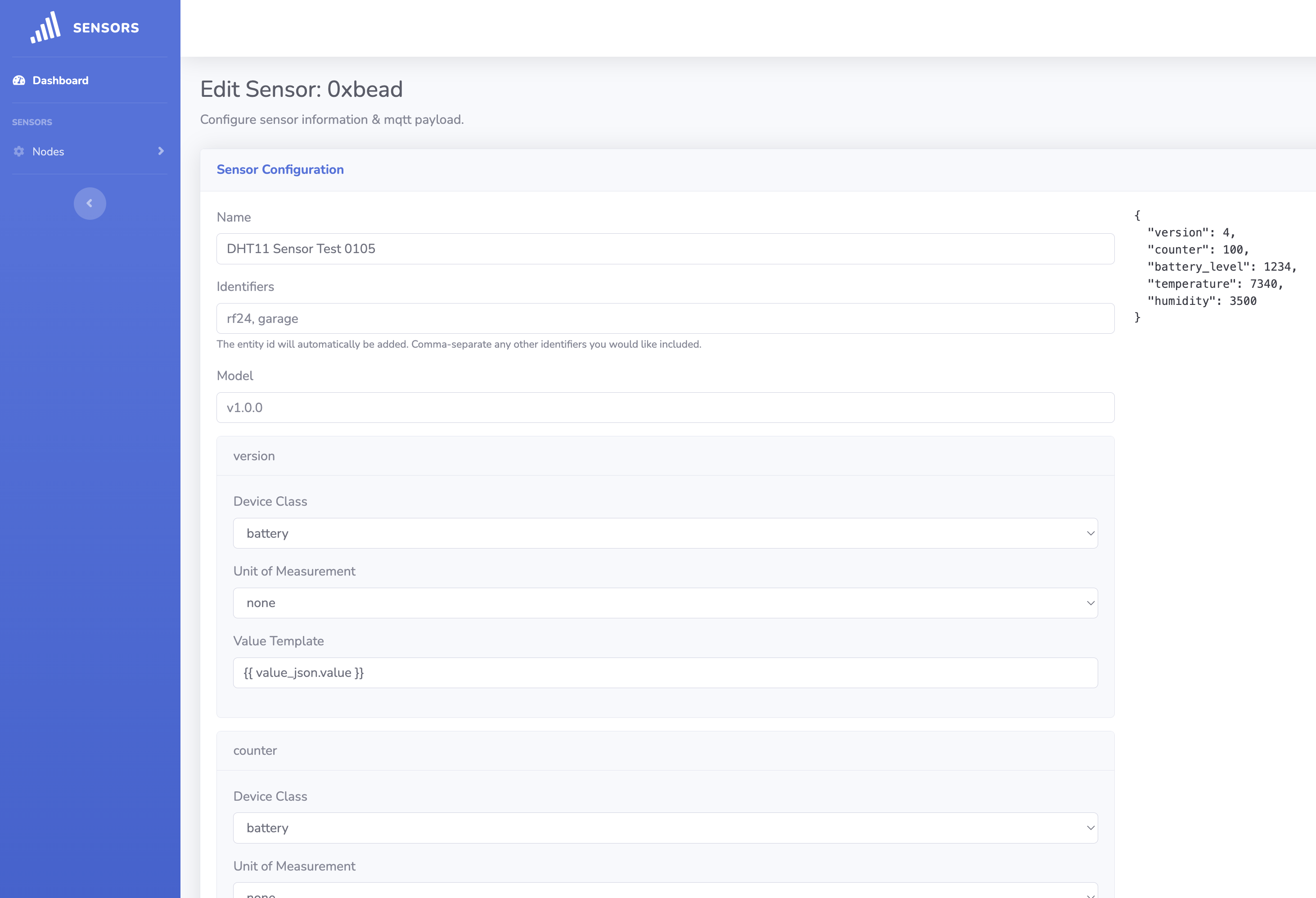
Using the Home Assistnat API, the controller uses the Home Assistant MQTT integration to register a new node and each field as devices. Notice in the screenshot above the field types / formatting templates match what is expected by Home Assistant, so I can do everything from the controller and the data just appears in Home Assistant.
# partial registration code
topic = "homeassistant/sensor/#{node.uuid}/battery_level/config"
payload = {
  name: 'Battery Level',
  unit_of_measurement: '%',
  value_template: '',
  state_class: 'measurement',
  state_topic: "homeassistant/sensor/#{node.uuid}/battery_level/state",
  unique_id: "#{node.uuid}_battery_level",
  icon: 'mdi:battery',
  device: {
    identifiers: [node.uuid],
    name: node.name,
    model: node.model,
    manufacturer: node.manufacturer
  }
}.to_json
mqtt.publish(topic, payload, retain: true)
Next Steps
I want to get everything into the github repo as soon as possible, which means rotating out existing nodes and getting fully switched over to the Xiao units and ESP-NOW transport. Some of my current nodes are still using NRF24 radios and need to be replaced. As I do that, I’ll write up details and start pushing code.
For the purpose of getting things usable by anyone crazy enough to follow along, I’ll also be updating my VPN config and will plan on using a raspberry pi to host the VPN, rails application, and Home Assistant.